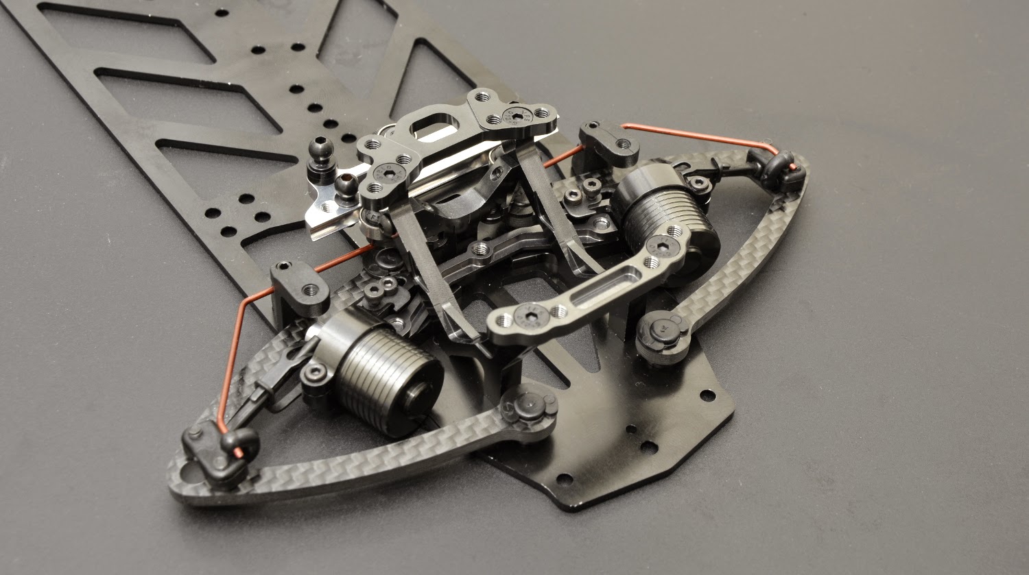
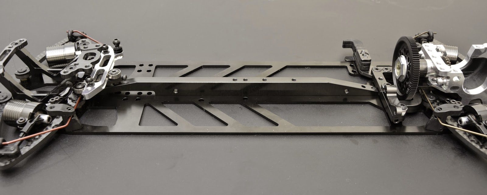
About a month ago I had the urge to upgrade my equipment so I chose to try one of my favorite brands, TEAM ORION.
They have come out with a few new goodies lately so I was eager to have them installed on my car.
The items I installed are:
Team Orion HMX 10 Modified speed control
Vortex Ultimate Modified 4.5T motor
Ultimate Graphene HV 7.6v 7.000 mAh LiPo battery
Vortex VDS2-HV XS servo
More HD photos here:
FLICKR PHOTO ALBUM
Showing posts with label EFRA. Show all posts
Thursday, 23 August 2018
Team Orion equiped
Labels:
1/10 scale,
1/10 tc,
4.5T,
A800,
Awesomatix,
belt car,
BRUSHLESS,
EFRA,
GRAPHENE,
HMX,
IFMAR,
LIPO,
MODIFIED,
Oleg,
Pole Position,
R10PRO,
TAMIYA,
TEAM ORION,
ULTIMATE,
Viljamin Kutvonen
Monday, 15 January 2018
Montech Racer body
Few months ago had the chance to try a RACER body from MONTECH. Much was said about this body and the test proved that it is an excellent product. Rigid, lightweight, aggressive design, and on average 0.150-0.300 faster than a PF LTCR on a very large asphalt outdoor track in cool-ish conditions for Greek standards and medium traction.
The track & the body.
Click on here for HD photos: Full Gallery

The track & the body.
Click on here for HD photos: Full Gallery

Monday, 16 November 2015
Awesomatix A800 - first look
The new Awesomatix A800 is hitting the stores shortly and soon many new lucky owners will enjoy it.
It is a departure of the shaft driven layout following now the trend of 2 belt driven cars.
Although a proven choice, Awesomatix has chosen to explore even further the posibilities to improve weight distribution and maximize the performance potential of the car.
By placing the spur gear on the right side (battery side) of the car, it allows to put the motor by 2mm further to the centre of the car as well as give direct access to the spur gear without the requirement of removing belts or upper deck. More on this later.
The entire transmission has been designed with the goal to be the lightest and most efficient possible. Low friction belts and pulleys help to achieve these goals as well as better reliability is achieved through the use of specific materials and well thought design.
Three chassis options are available. Here you can see the two of them. The one on top is a very nice aluminium hard anodized scratch resistant chassis with a lot of milling and a 3D shape where a concave effect is visible at the bottom of the chassis. This has proven to perform very well in many different conditions on carpet racing.The carbon chassis is a standard design with symmetrical milling on both sides of the main axis to produce even flex characteristics
The bulkheads are now 'keyed' in the chassis with integrated pins so they always perfectly align with the chassis' centreline
A beautiful aluminium diff housing also helps on keeping the oil cool and consistent.
Incredibly lightweight front spool !! Featherweight.
detail of the central pulley
Various optional central braces are available. On the photos of the assembled car you see the standard aluminium part. Here below is the heaviest available made of steel at 30 gr.
In my opinion one of the greatest improvements over the shaft kit is the ability to use the much proven dual bell crank steering design. It has super smooth and precise operation.
The one piece spur gear holder also incorporates an easy to install/remove single piece nut system. The replacement of the spur gear can be done by simply removing this nut and pulling upwards the spur, then place from the top the new spur, install the nut and you are done. No other part requires to be removed.
Labels:
1/10 scale,
A800,
belt car,
design,
EFRA,
IFMAR,
innovation,
Oleg,
race,
rc car,
unique,
Viljamin
Saturday, 10 January 2015
Awesomatix A700 Evo II - Presentation
And so it begins.
Step 1 - Steering hubs front & rear.
Front part
(Note: ST03 is a 5.0 mm ball stud, the one shown lower. ST24 is a 4.8 mm ball stud, the one shown on top)
Rear part
Step 2 - Drive axles
Front axle with double joint
ST17-1-S Universal ring set (option part). A very useful option for a much easier assembly of the double joints
Rear axle, single joint, but still ultra smooth.
Assembly on the steering blocks.
Front

Rear
Assembled sets
Step 3 - Arms installation.
The manual first guides you to install the steering blocks on the arms. I prefer to first assemble the arms on the chassis and thus make sure they have a free movement. This is important to achieve because even if the plastic caps (P03 ) mover freely on the arm holders (AT21), when the arm is screwed on the chassis the smallest of tolerances that may exist will still make the arm bind.
I first install the P06 part which houses the set screws for the droop settings. After I press them into the chassis I push them upwards and leave the least possible material sticking out the underside. I then apply a drop of CA (tire) glue and then I cut out the part protruding. I do this so that when I place the chassis on a perfectly flat surface, it stays flat and after each race or practice I can check if the chassis is bent.
The arm supports follow now. After I install the ST21 balls and push on them the P03 covers, I then install the arms and check for free movement. To eliminate end binding I press with a set of pliers the P03 covers and this perfectly helps to make movement completely free.
To secure the ST21 balls I use 6 or even 5 mm long screws since the chassis is a lot thinner than the older versions of the carbon chassis.
The roll bar holders and upstop limiters follow. The manual shows a 8 mm long screws. Again here you can use 6 or 5 mm long screws due to the thinner chassis.
Time for sway bars. Always make sure there is free movement, no binding and as little slop as possible.
Shock time. The dampers come pre-assembled with the SPR02 in the dampers. These are apparently hard pressed into the light colored aluminum shaft of the damper. To remove the SPR02 may require a lot of force. Try to swing it left right. You may also add a long screw into the thread of the shaft to use it as a handle to hold the entire piece while pulling out the SPR02.
After the SPR02 is removed you install the damper in its case AM17 and then re-install the SPR02. This time I had this part a little sanded with sand paper to make it slide in easier. This needs attention though cause if you remove too much material then it will move around and have slop.
When SPR02 is pushed in, a small part of it should exit the other side. This means it is centered and when the set-screw is installed to secure it, the SPR02 does not skew to either side, maintaining a perfectly central position, 90 degrees vertical to the shaft of the damper
These new dampers have a smaller range of motion. Below you can see its full range so make sure you build them accordingly.
Spring and shock rod installation
Central damper's brace. On this latest edition, the central screw with the two shims is no longer used. So don't look for a hole in the chassis for it. There isn't one! The brace holds the two dampers and itself by the two outer screws only.
Installation complete
Steering assembly. Simple as per the manual
Front FFG 1.1 assembly - Diff/Spool housing
FFG 1.1 front bulkhead
Place some 3M Scotch tape to minimize possible friction of the FFG shaft on the bulkhead.
There are 6 screws holding the bulkhead. I leave them loose and only tight them when I install it on the chassis to make sure that it is fixed properly and no tension is forced on the chassis making it tweak.
Front Diff/Spool assembly
I remove a very thin layer of material from the fin of lower cover to make sure it clears the chassis and allows free movement of the floating gear.
Now I fully tighten all screws on the bulkhead
UPDATE CORRECTION:
G03 Bevel Gear installation. Make sure to include the SPR06 wire ring. This will later on be used to hold the spur gear holder in place. As you see in the photos this SPR06 wire ring has a protruding edge. I found out I had to remove this to achieve a smooth free operating revolution of the G03 Bevel gear when the spur holders clicks inside.
Floating Motor Mount. One of the most impressive and innovative parts of the new kits. There are 4 different stiffness settings, depending on the number of screws used to hold the motor mount on the chassis. Obviously when you have no screws holding it, it is the softest setting.

The motor mount fastens on the rear bulkhead and it also holds the support for the battery holder
Floating Motor Mount shown from underneath
The very smart motor holder that attaches to the floating motor mount. The mesh of the pinion with the spur gear is controlled very easily by the side set screw. Brilliant!
The entire motor mount hanging. Zero interference with chassis flex
Spur gear holder. This is the standard part included in the kit. Same as previous kits
SD2 Spur damper set. This is the 2nd version of this trick part. It adds torsional flex between the spur axle and rear diff providing softer throttle and break reaction. In combination with the new main shaft (to be shown later on) it gives 'belt drive' properties on this shaft driven car.
UPDATE CORRECTION: It is important to install this correctly. I do not have an instruction manual since I got this kit early so I assembled this part the wrong way, twice!
After installing the damper shaft ST50 + ST47 into the spur holder AT20-5, you then install it in the rear bulkhead all the way through until it 'clicks' on the SPR06 ring of the G03 Bevel Gear. Make sure you are including the DT03 part, a small plastic stepped black tube piece. In my case it was a tight fit, and I understand it should be this way.
The SPR06 ring in some cases has a protruding edge. I removed this edge as I found out that when the ST47 part clicks through the ring it expands it and the ring's edge, if not removed, comes in contact with the inside of the bulkhead and the transmission binds.
On to the massive new main stiffener, AM33-5. It has multiple holes underneath for a variety of stiffness options, making it possible to alter the flex of the chassis according to race conditions.
The stiffener, at this stage, may be installed by sliding as shown below. It is a tight fit but it fits and sits very nicely, flat on the chassis.
The stiffener installed
Assembly of the FFG top deck or 'spine'. This time made out of aluminum. The carbon option is still available I think.
In order to make sure the FFG rod is assembled correctly I place it on a piece of glass upside-down in order to align the two main aluminum parts at each edge. After I do that then I slide it over to the edge of the glass, just enough to gain access to the set screws that secure the aluminum parts and I tighten them hard after I apply some pressure on the aluminum part and the rod itself to make sure they sit flat on the glass.
..and installed. Now it is crucial to have a smooth movement of the front diff left to right in the bulkhead. It is also important to have it centered, allowing for equal movement left to right. In my chassis I felt some binding. I had experienced that on my previous model as well. It is only very little that most users wouldn't bother with it but I wanted it to be perfect and I now know what may cause it. Some times the gap between parts AM41 (the Y shaped brace with the Scotch tape on it) and AM54-1 (the top part in which the bearing moves) is too tight. To solve this I use 0.3 mm shims between these two parts and the movement is silky smooth.
The gear diff. This is an upgraded version of what the previous kit had but it has been available for some time now as an optional part.
There aren't any tricks here. You simply assemble it as per the manual. It runs very smoothly and to my experience it has zero leakage. Very rarely you might need to slightly sand the back side of the gears, but it is not required.
The diff completed. The aluminum construction is very impressive and feels superb in your hand.
At this point I install the ST24 ball cups on the bulkheads, front & rear.
The central shaft. The original piece is a featherweight aluminum shaft. The option is a thicker, heavier shaft which in combination with the new SD2 Spur damper shown above it gives 'belt drive' properties to a very efficient shaft drive.
Installation couldn't be easier. Just slide in the rear end first in the spur holder and then 'click' the front end in the front gearbox. Done. Removal and replacement is similarly easy.
Floating servo mount. What was previously an option part it is now included in the kit.
It is common that these mounts may move just a tiny bit during running. A good solution is to scratch the surface of contact between the mount and the chassis. This increases friction considerably and the mount will never move again.
Servo mount and battery holders installed
Turnbuckles. Love them! .. not. At least they are not too hard to assemble. I use a bit of clear diff grease to make assembly easier, requiring less force.
And installed. When installing the steering blocks on the arms it is important to tighten the two SB25X8 screws of the ball holder as much as required to avoid slop but do not tighten fully if the movement is not free. It is easy to achieve zero slop with perfectly free movement. On the top of the steering block where the V arms made of two parts attaches on the ST0.3 (5.0mm) ball, if you notice tight movement you should do the trick with the pliers I did for on the P03 for the arm holders I mention at the beginning of the assembly.
Step 1 - Steering hubs front & rear.
Front part
(Note: ST03 is a 5.0 mm ball stud, the one shown lower. ST24 is a 4.8 mm ball stud, the one shown on top)
Front axle with double joint
ST17-1-S Universal ring set (option part). A very useful option for a much easier assembly of the double joints
Rear axle, single joint, but still ultra smooth.
Assembly on the steering blocks.
Front
Rear
Assembled sets
Step 3 - Arms installation.
The manual first guides you to install the steering blocks on the arms. I prefer to first assemble the arms on the chassis and thus make sure they have a free movement. This is important to achieve because even if the plastic caps (P03 ) mover freely on the arm holders (AT21), when the arm is screwed on the chassis the smallest of tolerances that may exist will still make the arm bind.
I first install the P06 part which houses the set screws for the droop settings. After I press them into the chassis I push them upwards and leave the least possible material sticking out the underside. I then apply a drop of CA (tire) glue and then I cut out the part protruding. I do this so that when I place the chassis on a perfectly flat surface, it stays flat and after each race or practice I can check if the chassis is bent.
To secure the ST21 balls I use 6 or even 5 mm long screws since the chassis is a lot thinner than the older versions of the carbon chassis.
The roll bar holders and upstop limiters follow. The manual shows a 8 mm long screws. Again here you can use 6 or 5 mm long screws due to the thinner chassis.
Time for sway bars. Always make sure there is free movement, no binding and as little slop as possible.
Shock time. The dampers come pre-assembled with the SPR02 in the dampers. These are apparently hard pressed into the light colored aluminum shaft of the damper. To remove the SPR02 may require a lot of force. Try to swing it left right. You may also add a long screw into the thread of the shaft to use it as a handle to hold the entire piece while pulling out the SPR02.
After the SPR02 is removed you install the damper in its case AM17 and then re-install the SPR02. This time I had this part a little sanded with sand paper to make it slide in easier. This needs attention though cause if you remove too much material then it will move around and have slop.
When SPR02 is pushed in, a small part of it should exit the other side. This means it is centered and when the set-screw is installed to secure it, the SPR02 does not skew to either side, maintaining a perfectly central position, 90 degrees vertical to the shaft of the damper
These new dampers have a smaller range of motion. Below you can see its full range so make sure you build them accordingly.
Central damper's brace. On this latest edition, the central screw with the two shims is no longer used. So don't look for a hole in the chassis for it. There isn't one! The brace holds the two dampers and itself by the two outer screws only.
Installation complete
Steering assembly. Simple as per the manual
Front FFG 1.1 assembly - Diff/Spool housing
FFG 1.1 front bulkhead
Place some 3M Scotch tape to minimize possible friction of the FFG shaft on the bulkhead.
There are 6 screws holding the bulkhead. I leave them loose and only tight them when I install it on the chassis to make sure that it is fixed properly and no tension is forced on the chassis making it tweak.
Front Diff/Spool assembly
I remove a very thin layer of material from the fin of lower cover to make sure it clears the chassis and allows free movement of the floating gear.
Now I fully tighten all screws on the bulkhead
UPDATE CORRECTION:
G03 Bevel Gear installation. Make sure to include the SPR06 wire ring. This will later on be used to hold the spur gear holder in place. As you see in the photos this SPR06 wire ring has a protruding edge. I found out I had to remove this to achieve a smooth free operating revolution of the G03 Bevel gear when the spur holders clicks inside.
Floating Motor Mount. One of the most impressive and innovative parts of the new kits. There are 4 different stiffness settings, depending on the number of screws used to hold the motor mount on the chassis. Obviously when you have no screws holding it, it is the softest setting.
The motor mount fastens on the rear bulkhead and it also holds the support for the battery holder
Floating Motor Mount shown from underneath
The very smart motor holder that attaches to the floating motor mount. The mesh of the pinion with the spur gear is controlled very easily by the side set screw. Brilliant!
The entire motor mount hanging. Zero interference with chassis flex
Spur gear holder. This is the standard part included in the kit. Same as previous kits
SD2 Spur damper set. This is the 2nd version of this trick part. It adds torsional flex between the spur axle and rear diff providing softer throttle and break reaction. In combination with the new main shaft (to be shown later on) it gives 'belt drive' properties on this shaft driven car.
UPDATE CORRECTION: It is important to install this correctly. I do not have an instruction manual since I got this kit early so I assembled this part the wrong way, twice!
After installing the damper shaft ST50 + ST47 into the spur holder AT20-5, you then install it in the rear bulkhead all the way through until it 'clicks' on the SPR06 ring of the G03 Bevel Gear. Make sure you are including the DT03 part, a small plastic stepped black tube piece. In my case it was a tight fit, and I understand it should be this way.
The SPR06 ring in some cases has a protruding edge. I removed this edge as I found out that when the ST47 part clicks through the ring it expands it and the ring's edge, if not removed, comes in contact with the inside of the bulkhead and the transmission binds.
On to the massive new main stiffener, AM33-5. It has multiple holes underneath for a variety of stiffness options, making it possible to alter the flex of the chassis according to race conditions.
The stiffener, at this stage, may be installed by sliding as shown below. It is a tight fit but it fits and sits very nicely, flat on the chassis.
The stiffener installed
Assembly of the FFG top deck or 'spine'. This time made out of aluminum. The carbon option is still available I think.
In order to make sure the FFG rod is assembled correctly I place it on a piece of glass upside-down in order to align the two main aluminum parts at each edge. After I do that then I slide it over to the edge of the glass, just enough to gain access to the set screws that secure the aluminum parts and I tighten them hard after I apply some pressure on the aluminum part and the rod itself to make sure they sit flat on the glass.
..and installed. Now it is crucial to have a smooth movement of the front diff left to right in the bulkhead. It is also important to have it centered, allowing for equal movement left to right. In my chassis I felt some binding. I had experienced that on my previous model as well. It is only very little that most users wouldn't bother with it but I wanted it to be perfect and I now know what may cause it. Some times the gap between parts AM41 (the Y shaped brace with the Scotch tape on it) and AM54-1 (the top part in which the bearing moves) is too tight. To solve this I use 0.3 mm shims between these two parts and the movement is silky smooth.
The gear diff. This is an upgraded version of what the previous kit had but it has been available for some time now as an optional part.
There aren't any tricks here. You simply assemble it as per the manual. It runs very smoothly and to my experience it has zero leakage. Very rarely you might need to slightly sand the back side of the gears, but it is not required.
The diff completed. The aluminum construction is very impressive and feels superb in your hand.
At this point I install the ST24 ball cups on the bulkheads, front & rear.
The central shaft. The original piece is a featherweight aluminum shaft. The option is a thicker, heavier shaft which in combination with the new SD2 Spur damper shown above it gives 'belt drive' properties to a very efficient shaft drive.
Installation couldn't be easier. Just slide in the rear end first in the spur holder and then 'click' the front end in the front gearbox. Done. Removal and replacement is similarly easy.
It is common that these mounts may move just a tiny bit during running. A good solution is to scratch the surface of contact between the mount and the chassis. This increases friction considerably and the mount will never move again.
Servo mount and battery holders installed
Turnbuckles. Love them! .. not. At least they are not too hard to assemble. I use a bit of clear diff grease to make assembly easier, requiring less force.
And installed. When installing the steering blocks on the arms it is important to tighten the two SB25X8 screws of the ball holder as much as required to avoid slop but do not tighten fully if the movement is not free. It is easy to achieve zero slop with perfectly free movement. On the top of the steering block where the V arms made of two parts attaches on the ST0.3 (5.0mm) ball, if you notice tight movement you should do the trick with the pliers I did for on the P03 for the arm holders I mention at the beginning of the assembly.
Labels:
1/10 scale,
A700,
assembly,
Awesomatix,
EFRA,
evo II,
IFMAR,
ISTC,
Oleg,
open mod.,
racing car,
TC,
Viljamin Kutvonen
Subscribe to:
Posts (Atom)